
In this corridor is my photo-journal and a list of my physical computing bookmarks
10/01/05 Pier11
11/07/05 The Lighting Project
11/21/05 NomadAV
09/18/05
Over the past couple of days, I soldered pieces of wires together to get the hang of it. I stared at the beardboard for a while Since i am a pen and paper person, i kept on wanting to draw out what i needed to do. But i wanted to play with the elements to get a feel for them. I started by going over my notes and browed around the various weblinks on the pcomp site just to make sure of what i was doing and fired up the soldering iron. I built 4 power connectors. So far, that was easy.
09/21/05
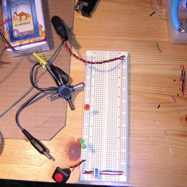
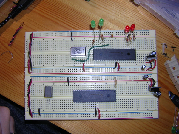
I used one board set-up that i knew worked, to build the microchip prototype. Since i'm using the 20Mhz ocsillator clock, it took me a while to figure out the wiring and resistance. A 2nd-year, showed me that if i move the power supply into bus 2 or 3, I can plant a 10ÊF-> 5V resistor ->1ÊF, the latter being in the 4th bus. I have the power feeding into the PIC18F4525-I/P and back out to ground on the right side of the chip. THe 20Mhz clock is pinned below the PIC with power coming from Bus 4 (top right pin) and grounded in bus1 (bottom left pin). I used a green wire to connect the PIC( OSC1) to the bottom right pin of the clock. A small 22 capacitator is plugged to OSC1 and bus1 ground.
I am using 2 green LEDs and 2 red LEDs with 220¶ resistor per LED. A 10K¶ resistor links Pin1 (MSTRCLR) to the power of bus1.
Note: i pulled 5V power from the 3rd leg of the resistor to bus 1 and 4.
Now i'm going to program with Basic and hope for the best.
| Dee092105a |
|---|
DEFINE osc20 OUTPUT portC.3 PAUSE 500 Main: HIGH portC.3 PAUSE 200 HIGH portC.3 PAUSE 200 HIGH portC.3 PAUSE 200 HIGH portC.3 PAUSE 200 HIGH portC.3 PAUSE 200 HIGH portC.3 PAUSE 200 HIGH portC.3 PAUSE 200 HIGH portC.3 PAUSE 200 HIGH portC.3 PAUSE 200 HIGH portC.3 PAUSE 200 |
'(x10) and then stop.
That didn't work. But the reason was not a code problem. I forgot to ground bus1. Basically, I was short-circuiting my board and elements (again). No damage was done. I was glad about that and also that every other elements were wired correctly and the codes were right the first time around. What I wanted from my code was for the LED on portC.3 to blink. I realized after typing the code above, all i would get was a LED that would stay on. But that suited me fine AS I GOT MY LED TO LIGHT UP!!!! What a good feeling after 5 hours of brain twisting.
Here are some more codes i will try out in the tech lab tomorrow:
| Dee092105b(blink) | Dee092105c(4LEDs) | Dee092105d(4LEDblink) |
|---|---|---|
DEFINE osc20 OUTPUT portC.3 PAUSE 500 Main: HIGH portC.3 PAUSE 200 LOW portC.3 PAUSE 200 HIGH portC.3 PAUSE 200 LOW portC.3 PAUSE 200 GOTO Main |
DEFINE osc20 OUTPUT portC.3 OUTPUT portD.1 OUTPUT portA.3 OUTPUT portA.4 PAUSE 500 Main: HIGH portD.1 PAUSE 500 LOW portD.1 PAUSE 500 HIGH portC.3 PAUSE 500 LOW portC.3 PAUSE 500 HIGH portA.4 PAUSE 500 LOW portA.4 PAUSE 500 HIGH portA.3 PAUSE 500 LOW portA.3 |
DEFINE osc20 OUTPUT portC.3 OUTPUT portD.1 OUTPUT portA.3 OUTPUT portA.4 PAUSE 500 Main: HIGH portD.1 PAUSE 200 LOW portD.1 HIGH portC.3 PAUSE 200 LOW portC.3 HIGH portA.4 PAUSE 200 LOW portA.4 HIGH portA.3 PAUSE 200 LOW portA.3 GOTO Main |
09/29/05
The first code I ran (left column above) on the chip I got warning messages in the results dialogue box. The few words are "CONFIG, has been depreciated for PIC18 devices. Use directive config". It didn't work in the board. I erased the chip independently from the program option. I reprogrammed it and now it happily blinks away. Next code.
The code in the middle column did not work. Note: I changed port A.3 and A.4 to D.2 and C.4. If I would forget to unplug the power, the LEDs in port c.3 and d.1 blinked once when i replaced the chip. Of course i changed the ports in the code. no compredo. in a futile attemp, i even tried to select 4520 and 4525 in addition to its normal model number. I'll try the next one. ( i'm getting sleepy...) well, no actually it's the same code. The pause length is the only thing that changes and that the program is looped. Oh well.
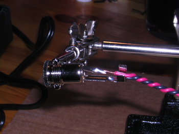
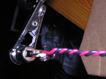
I did the worst job soldering the head to the serial plug. I'm afraid my soldering points are too close and are touching.
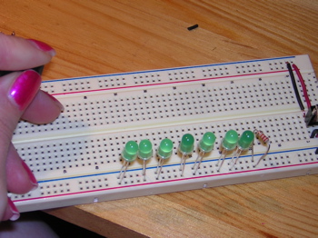
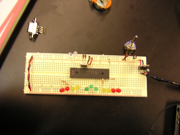
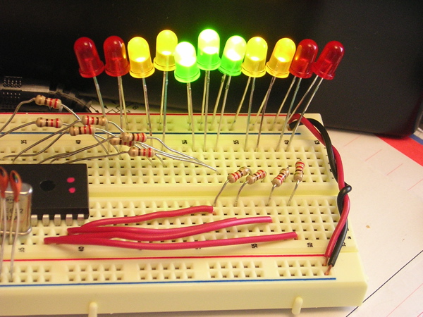
09/29/05 Let's try another board and chip with 13 LEDs.
| Dee092905a |
|---|
DEFINE osc4 OUTPUT portC.3 OUTPUT portD.1 PAUSE 500 start: HIGH portc.3 PAUSE 500 LOW portc.3 HIGH portd.1 PAUSE 500 LOW portd.1 |
IT"S ALIVE!!!! it wouldn't work at first untill i moved the ground wire out of power into ground(hahaha)( look at picture above). Actually, the funny thing is that the code is not looped but it cycles thru the code indefinitely.
One more for the road:
| Dee092905b |
|---|
DEFINE osc4 OUTPUT portc.2 'red OUTPUT portc.3 'red OUTPUT portd.0 'yellow OUTPUT portd.1 'yellow OUTPUT portd.2 OUTPUT portd.3 OUTPUT portc.4 'green OUTPUT portc.5 'green OUTPUT portc.6 'green OUTPUT portc.7 OUTPUT portd.4 'yellow OUTPUT portd.5 'yellow OUTPUT portd.6 'red OUTPUT portd.7 'red PAUSE 500 start: HIGH portc.2 'red HIGH portc.3 HIGH portd.6 HIGH portcd.7 PAUSE 500 LOW portc.2 LOW portc.3 LOW portd.6 LOW portd.7 HIGH portd.0 'yellow HIGH portd.1 HIGH portd.4 HIGH portd.5 PAUSE 500 LOW portd.0 LOW portd.1 LOW portd.4 LOW portd.5 HIGH portc.4 'green HIGH portc.5 HIGH portc.6 PAUSE 500 LOW portc.4 LOW portc.5 LOW portc.6 HIGH portd.0 'yellow HIGH portd.1 HIGH portd.4 HIGH portd.5 PAUSE 500 LOW portd.0 LOW portd.1 LOW portd.4 LOW portd.5 GOTO start |
"...And now for something completely different..."
KIT2005
note: if the movie is not playing press the refresh button.
Last updated: 11/06/05